Benefits of synchronized FM emissions
Using Synchronized FM transmitters operating on the same frequency («FM Isofrequency» - «FM Isomodulation» - «FM SFN») it is possible to extend the coverage area of a main transmitter to neighboring areas, with some limitations and precautions.
The advantages offered by this technology are considerable:
- The need for significantly lower protection ratios than non-synchronized emissions (up to be able to accept, under certain conditions, differences in level of less than 1dB!)
- More efficient use of the electromagnetic spectrum having the ability to cover poorly served areas at the limits of a main service area without having to use a different frequency, thus optimizing the use of the frequencies themselves (Gap-Filler)
- An additional powerful tool for planning and optimizing FM broadcast networks
The protection ratio normally required
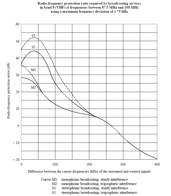
The ITU-R BS.412-9 recommendation, for the purpose of FM service planning, defines the necessary protection ratios between two different frequency modulation signals and/or not synchronized with each other, according to:
- Frequency difference
- Emission mode (mono or stereo)
- Continuity of the interference (tropospheric or steady)
You can see that, in case of steady interference and same frequency (channel), the minimum protection ratio required is 36dB for monophonic broadcasting and 45dB for stereophonic broadcasting.
Qualitative Levels of an Audio Signal
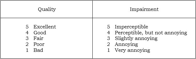
The ITU-R BS.562-3 recommendation, in order to define the acceptability of the quality level of an audio signal, classifies the degradation (Impairment) with a 5-level scale: from the best (5) to the worst (1).
Normally, in addition to level 5 (a perfect signal), level 4 is accepted (defined as «good» because the impairment is described as «perceptible, but not annoying») and, at least, level 3 is accepted, for example, for reception in cars (defined as «fair» because the impairment is only «slightly annoying»).
Protection ratios in Isofrequency
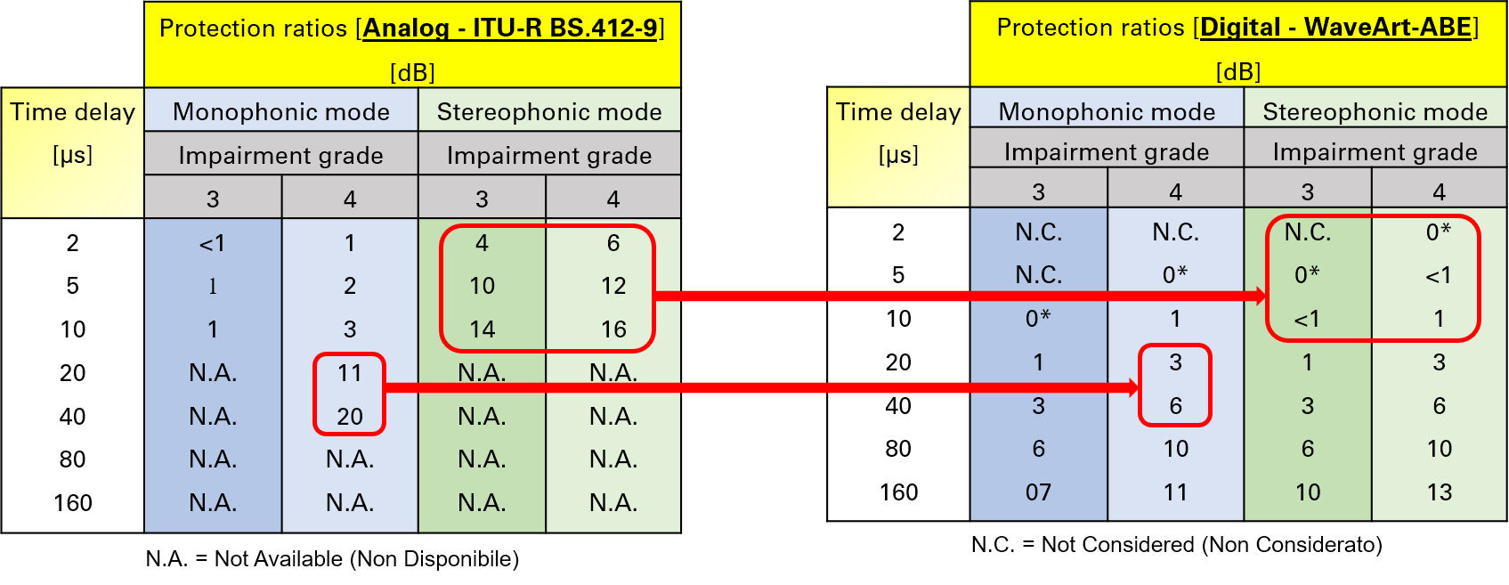
The ITU-R BS.412-9 recommendation defines the necessary protection ratios between two Isofrequency and Isomodulation signals as a function of the delay to reach the receiving point (path difference), the emission mode (mono or stereo) and the quality level (degradation – Impairment grade).
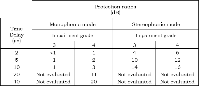
With reference to the data obtained from the ITU-R BS.412-9 recommendation, Isofrequency and Isomodulation signals with path difference (delay) of 4Km (13.2µs), need a protection ratio of approximately 25 dB instead of the 45dB normally required between unsynchronized stereo signals.
Of course, with lower delays (path differences), the protection ratio is further reduced.
The ITU-R BS.412-9 Recommendation dates back to 1998. The tests were conducted in the previous years using an "Analog“ implementation of the Isofrequency/Isomodulation emissions and with the FM receivers available on the market at that time.
The tests of the new WaveArt-ABE implementation have been conducted in a similar way to those of the ITU-R BS.412-9 Recommendation, but with “Digital" Isofrequency/Isomodulation transmitters and with current FM receivers: results were considerably better than those reported in ITU Recommendation (see table here below).
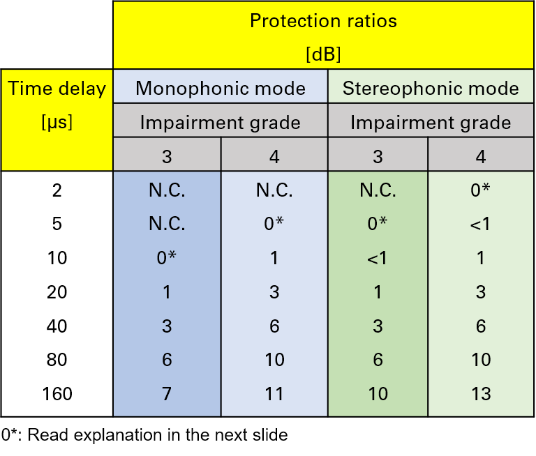
The tests were conducted with receivers equipped with stereo blend (as in almost all car radios) and with a frequency difference between the transmitters of 0.13Hz (phase rotation between the signals of 360° in about 7 seconds), in order to also evaluate the disturbances due to phase difference.
Comparison between different implementations
As better specified above, the results reported in the Recommendation ITU-R BS.412-9 (1998 - made with «analog» Isofrequency implementation and with transmission and reception technologies available at the time) are enormously different from the results obtained in the current tests by adopting the WaveArt-ABE solution with the «digital» implementation described in this tutorial.
The requirements of Synchronized FM emissions
This point must be absolutely clear, as there are many partial implementations that, obviously, do not give the desired results.
Synchronized FM emissions must meet ALL of the following requirements:
- The transmitters must emit on the same channel and have precisely the same frequency (for example, with GPS locked reference oscillators).
- They must transmit the same IDENTICAL modulation content, meaning not only the transmission of the same program, but the exact same modulation «footprint» (same modulation peaks with same precise deviation to the Hz, in the same moment, etc.).
This result is practically impossible to obtain with two different analog modulators or, in any case, with two FM modulators - even with digital processing - but fed by analog signals.
- They must have a delay compensation to simultaneously deliver the signals emitted into the double serviced area (the potentially interfered area) in order to benefit from this technology.
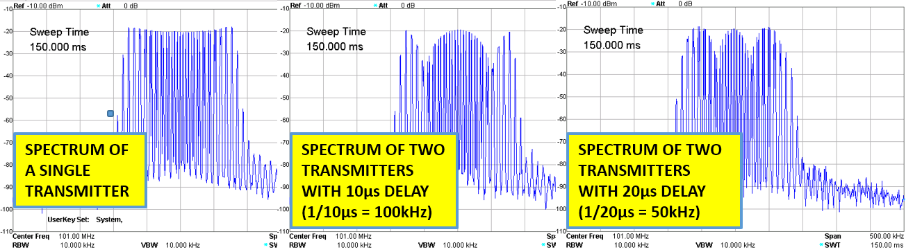
A simple method to verify Isofrequency
By analyzing the spectrum of two transmitters with the summed RF output, one can easily verify whether the emissions have been correctly generated in Isofrequency/Isomodulation.
It is sufficient to modulate the carriers with a mono audio tone (e.g.: 500Hz) and, depending on the difference in delay and level of the two RF modulated signals, "holes“ (notches) can be observed in the spectrum. Distance and depth of the notches are a function of the differences of delay and amplitude (greater difference of delay generates closer notches, while the smaller the difference in amplitude, the deeper the notches are).
«Analog» FM Isofrequency
To benefit from all the advantages previously described it is necessary that the implementation meets all the necessary requirements.
The implementation can be done in «analog» mode (see the ABE Elettronica patent filed in 1989) using microwave links that transfer a FM modulated subcarrier, that is converted to the emission frequency (87.5 - 108MHz) with an oscillator synchronized by another signal transferred by the same microwave links. In this case, the delay compensation takes place with analog delay lines acting on the FM modulated subcarrier. The main drawbacks of this system are the high bandwidth occupation of the microwave links (over 10MHz) and the cost of analog delay lines.
Another even more expensive "analog" implementation made by RAI is based on the use of optical fiber for the transfer of the modulated FM carrier.
“Digital" FM Isofrequency made by WaveArt-ABE
Nowadays the use of "digital" techniques allows implementations of synchronized FM emissions that are much more efficient than those made in the past with "analog" technologies.
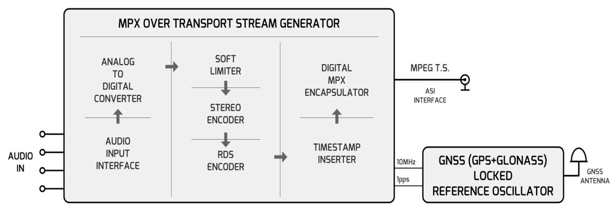
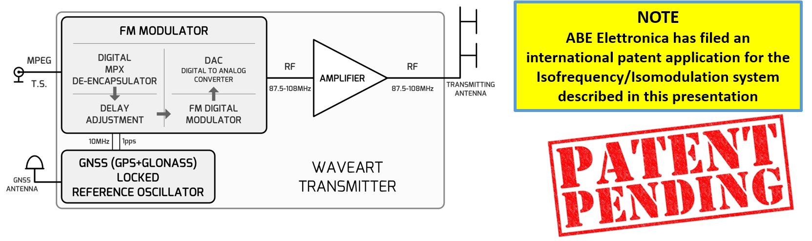
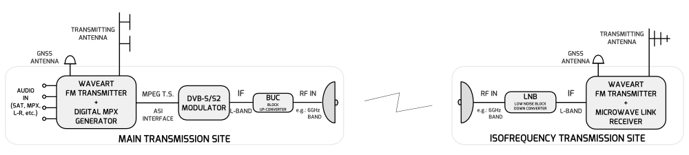
The implementation developed by WaveArt with ABE Elettronica is based on the following technologies:
- The generation of a digital MPX signal (mono or stereo + RDS) whose data flow (about 2Mbit/s) is encapsulated in a Transport Stream MPEG with ASI interface or other
- The insertion in the Transport Stream of a «Time Stamp» for the synchronization of the emissions
- The insertion in the Transport Stream of a time offset data (Network delay) to take into account the latency with which the digital MPX data flow reaches all transmitters in the Isofrequency network
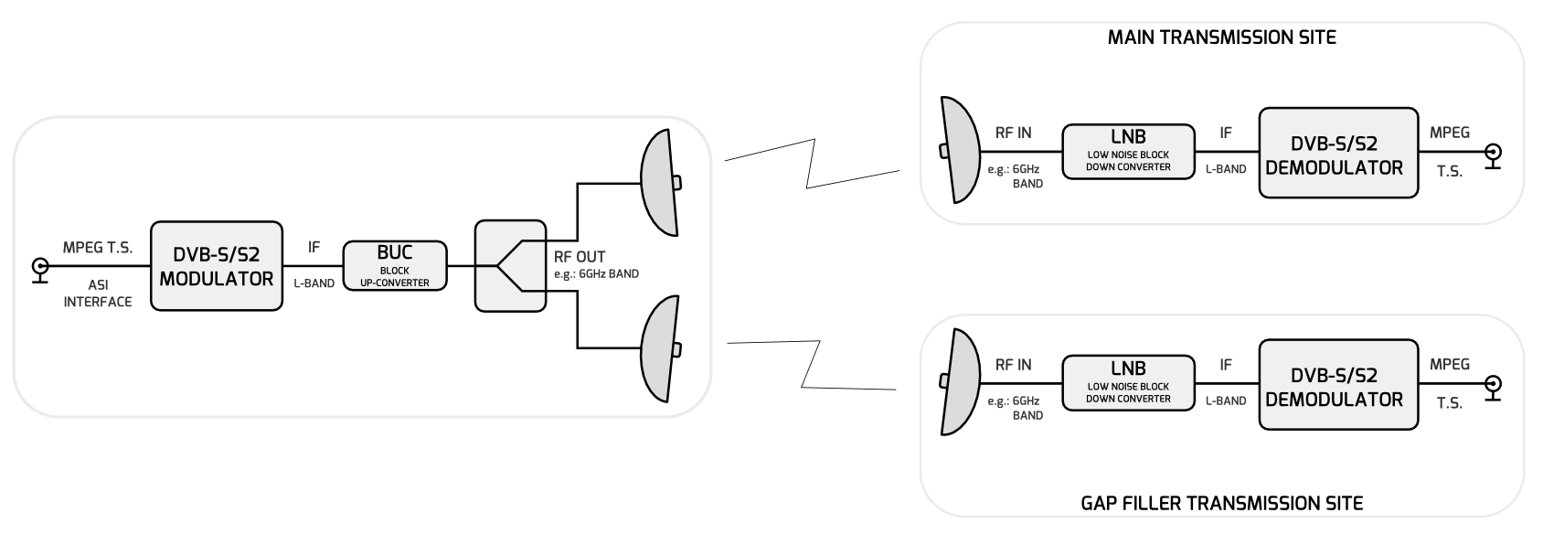
- The transfer, through digital microwave links (terrestrial or satellite), of the MPX data stream (Transport Stream) to the FM transmitters in the Isofrequency/Isomodulation network
- The use, in all transmitters, of an adjustable digital memory (FIFO) to synchronize the digital MPX received with the «Time Stamp» contained in the Transport Stream, to compensate the Network Delay and the delay with which the emissions reach the potentially interfered area
- The modulation (digitally carried out in all transmitters) of the carrier at the emission frequency (87,5 – 108 MHz)
- The synchronization of all the system (MPX data, Time Stamp, FM emission carriers) to the same reference (UTC second received through GPS/GLONASS - using proprietary algorithms)
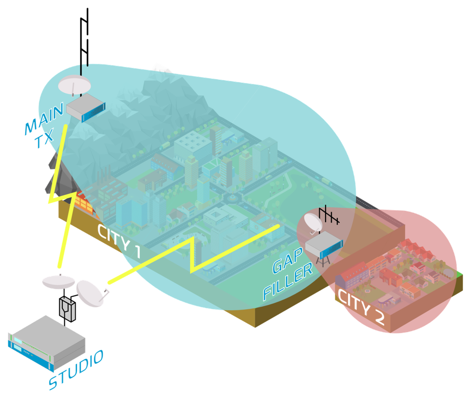
The best implementation of the Isofrequency
In this implementation example, the synchronized Gap Filler covering the «City 2» at the edge of the coverage area of the main Transmitter, has a directive antenna radiating the signal in the same direction as that coming from the main Transmitter.
In this way, in the dual-serviced area a sufficiently constant delay between the two emissions is maintained, allowing to benefit from the advantages of the FM Synchronized emissions (significantly lower protection ratios).
With reference to the previous picture, the delay differences of the signals coming from the main Transmitter and the Gap Filler arriving in the «City 2» (in particular at its edges, where the difference of delay is greater), are between 0 and 1.9μs.
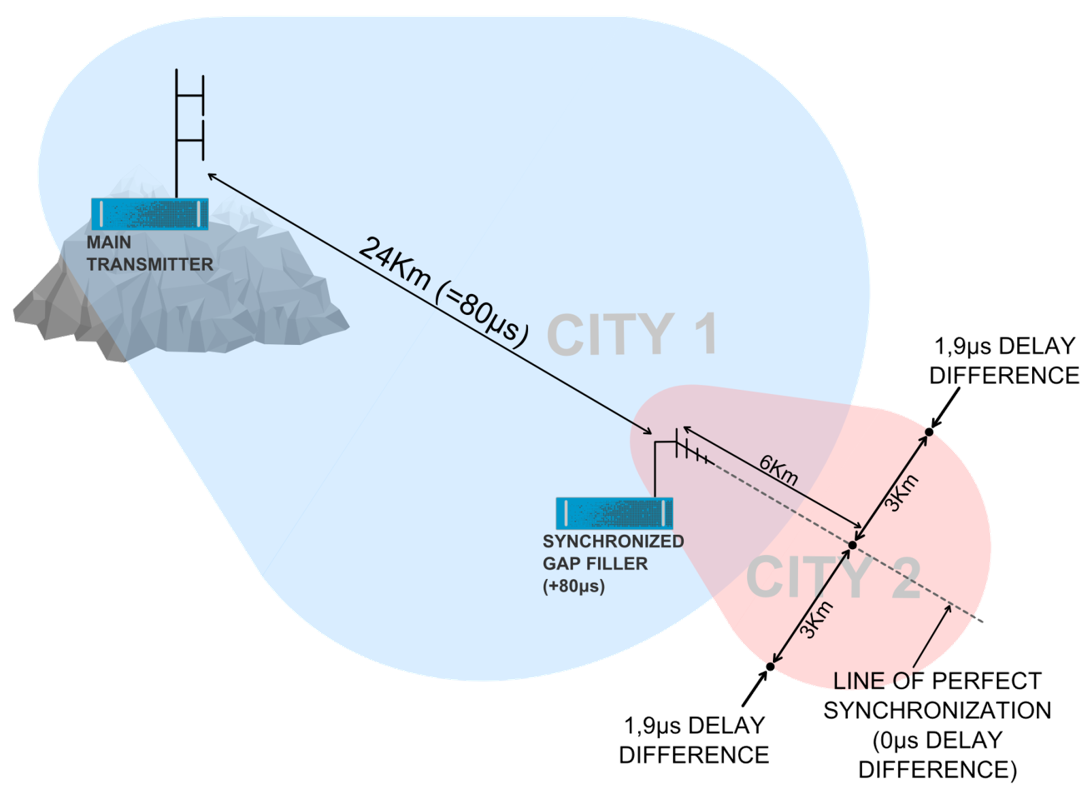
This means that, to have an «Impairment Grade» equal to 4 (signal defined as “good” with “perceptible but not disturbing degradation”), it is not necessary to have any level difference between the two signals, based on test results of the new WaveArt-ABE implementation.
This is the best possible implementation of Isofrequency system.
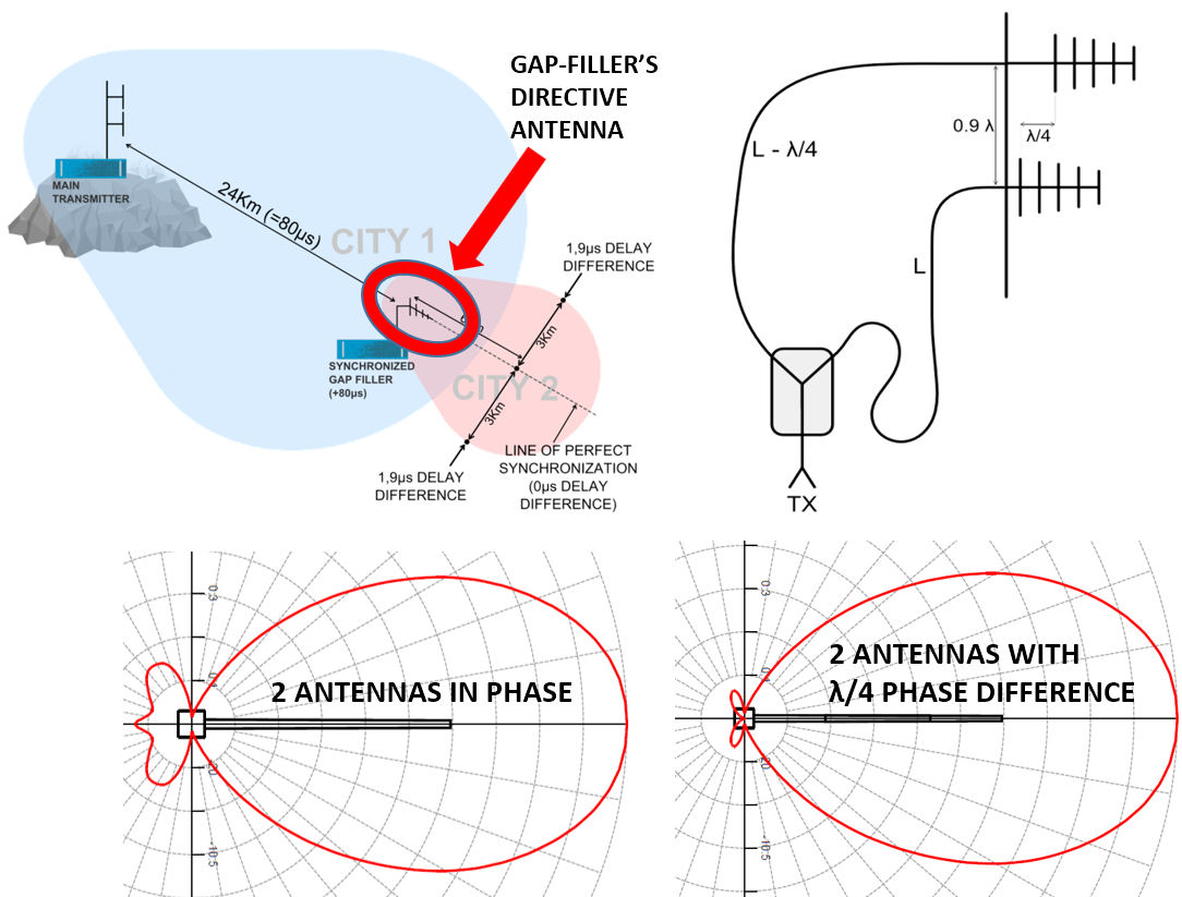
With reference to the previous slide, it is advisable that the front/back ratio of the Gap Filler’s directive antenna is high, in order to reduce interference towards the main transmitter.
A method to obtain this result is to use two directive antennas, oriented in the same direction and placed one below the other at about 0.9 λ.
The upper antenna must be advanced λ/4 (about 75 cm) with respect to the other and have the connection cable to the antenna divider at -90° offset (-λ / 4) with respect to the other cable.
In this way, the front/back ratio of the system with two antennas improves of about 20dB.
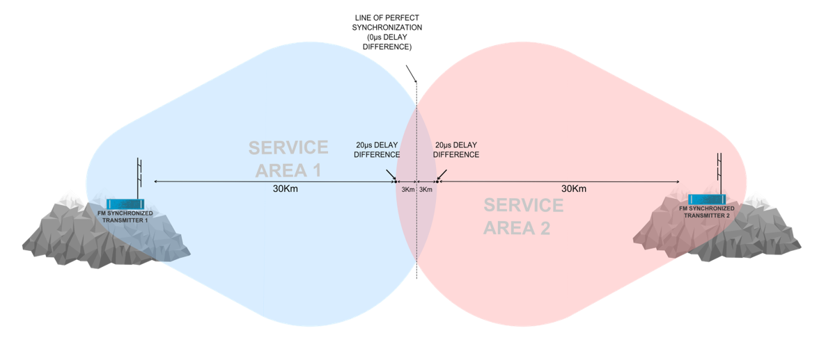
A possible implementation of Isofrequency
In this example of implementation, the delays with which the signals of the two synchronized transmitters arrive in the area of potential interference (in particular at the margins of the same, where the difference of delay is greater and that we have assumed to be 6km as in the previous example), are between 0 and 10µs.
This means that, to have an «Impairment Grade» equal to 4 (signal defined as “good” with “perceptible but not disturbing degradation”), it is necessary to have a level difference between the two signals of only 1dB, based on test results of the new WaveArt-ABE implementation.
This is only possible with well-calculated and structured antennas.
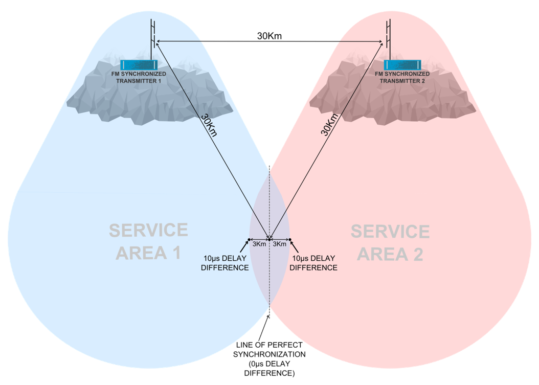
A more complex implementation
In this example of implementation, with transmitters in opposite directions, the delays with which the signals of the two synchronized transmitters arrive in the central interference zone (in particular on the margins of the same, where the difference of delay is greater and that we have assumed to be always 6km as in the previous example), are between 0 and 20µs.
This means that, to have an «Impairment Grade» equal to 4 (signal defined as “good” with “perceptible but not disturbing degradation”), it is necessary to have a level difference between the two signals of 3dB, based on test results of the new WaveArt-ABE implementation.
This is possible, despite some difficulties, only with well-calculated and structured antennas.
This implementation of Isofrequency is the most difficult to achieve.
Further benefits of WaveArt-ABE Isofrequency
The consistent quality improvement with the digital transfer of the MPX signal
Currently, most backhauling systems (signal transfer from radio studios to transmitting sites) use analog MPX microwave links in the 900MHz or 2GHz band, with all the related problems (frequency overcrowding, noise, degradation of the C/N ratio and stereo separation, etc.).
Even those who use the satellite for backhauling still find the degradation due to compression and decompression of the audio channels, to overshoots (again due to compression/decompression, which cause unwanted peaks of modulation often “out of mask"), etc.
The solution for backhauling developed by WaveArt-ABE, in addition to making possible the implementation of Isofrequency, solves all the problems mentioned above, as it digitally transfers (at high resolution – 16bit) the uncompressed MPX signal through digital terrestrial (or satellite) links that require a C/N of only 6 or 7 dB (standard implementation) to have an error-free reception (perfect quality, very high signal-to-noise ratio, no degradation in repetitions, etc.).
These links are available on different frequency bands and may have a channel bandwidth even below 1MHz (the standard channel bandwidth required is 1.75MHz).
The insertion of the «Time Stamp» and the «Network Delay» data in the MPX
The system developed by WaveArt-ABE provides for the insertion, in the data stream of the digitalized MPX (Transport Stream), of a time stamp referred to the UTC second (by means of reception/synchronization with GNSS - GPS/GLONASS carried out with proprietary algorithms) to facilitate synchronization of the transmitters in the Isofrequency network and, in case of use of a satellite connection for the backhauling, to make it possible. In addition, it is inserted a «time offset» data to allow the flow of the MPX data to reach all the transmitters in the Isofrequency/Isomodulation network and to be processed thus allowing the correct emission timing and therefore, the consistency of synchronized emissions.
The use of the «Time Stamp» and the «Network Delay» data allow the adjustment of the latencies necessary for the correct implementation of the Isofrequency only to the delays between the transmitters and the potentially interfered area, automatically absorbing the latencies and any instability due to the backhauling (signals transfer by means of links or other).
Systems that do not have a similar mechanism for synchronization make it quite difficult (nearly impossible) the synchronization itself and to keep it constantly.
The implementation of the Isofrequency with backhauling via satellite
The so-called "geostationary" communication satellites orbit over the Equator at about 36,000km from the Earth's surface. Their angular speed is equal to the one of the terrestrial rotation, so they have the effect of being "stationary" with respect to the earth's surface.
Actually, in spite of the term "geostationary", satellites are not really "stationary" but, because of the "solar wind" and other, they move very slowly and are, from time to time, re-positioned by means of on-board small rockets. Satellites typically move within an imaginary cube having about 50 kilometers of side. This means that the overall path of the RF signal from Earth to Satellite and vice-versa can vary even of 100Km (equivalent over time to more than 300μs), depending on where the satellite is located.
Therefore, satellite links can not be considered to have stable latency (as the connections with terrestrial microwave links) and cannot be used, without constant corrections in an FM Isofrequency system that requires precision and stability of a few tenths of a microsecond.
The system developed by WaveArt-ABE, by means of the "time stamp" inserted in the Transport Stream and the GNSS synchronization (GPS + GLONASS) carried out with proprietary algorithms, compensates the instability of the satellite making it possible to use it also in FM Isofrequency networks.
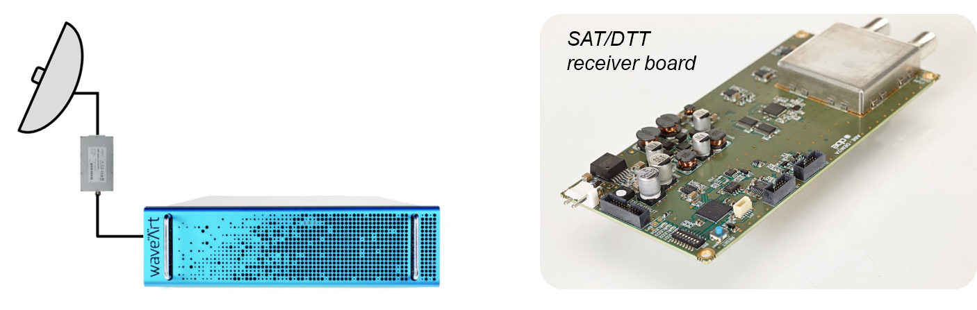
Satellite and Microwave Link receiver on board WaveArt Transmitters
The system developed by WaveArt in cooperation with ABE allows the integration of the satellite or microwave link receiver in the FM transmitters, thus allowing a simplification in the installations, an economic saving and the possibility to have the receiver controls integrated in the transmitter telemetry.
For the reception, only the antenna (usually a dish) and a suitable LNB (Low Noise Block downconverter) has to be installed.
The "light" implementation of the Isofrequency
The modulator board inside the WaveArt transmitter can be used simultaneously to transmit the FM Isofrequency signal and to generate the Transport Stream with the digital MPX data flow with Time Stamp and Network Delay to be sent to one or more other transmitters in Isofrequency operation.
In this way an extremely simplified (and less expensive) configuration can be built for the implementation of the Isofrequency, without going to affect the entire structure of an existing FM transmitter network, but implementing the Isofrequency only between the transmitters where necessary.
GNSS Locked Timing Reference
The UTC timing information available receiving GPS and GLONASS satellites
ABE GNSS Locked Timing Reference (1PPS + 10MHz) employ proprietary algorithms that have been specifically developed to generate and maintain frequency and timing stability in any condition and to prevent telecommunication networks de-synchronization that often happens using standard products, not specifically developed for this purpose.
Main features include:
- High sensitivity 32 channels GNSS (GPS + GLONASS) receiver specific for the timing function
- Fast satellites acquisition and single satellite operation capability
- Fast cold start-up function
- Long term «Zero cumulated error» function
- Holdover error recovery function (the timing error accumulated during the holdover period is slowly compensated, so re-synchronizing the modulators)
- Hi stability 10MHz oven oscillator allowing long holdover time in case of lack of GNSS signals
For more detailed information, please see also the «GNS 1000» presentation available on www.abe.it